Technical Support
Table of Contents
Most welder problems are caused by issues outside the welder cabinet. These issues are usually associated with AC input power or the gun and cables. It is important to confirm the integrity and operation of both these systems before opening the cabinet.
An electrical test meter with settings for AC and DC voltage as well as continuity (or resistance) is needed. AC power is dangerous and must be handled safely. Be careful when confirming power and wiring to the welder. The guns while not electrically unsafe are still a hazard. Sparks may be thrown by the gun electrodes during welding. Protect the eyes from flying sparks and the skin from accidental burns from hot gun components.
Confirming Welder Supply Voltage
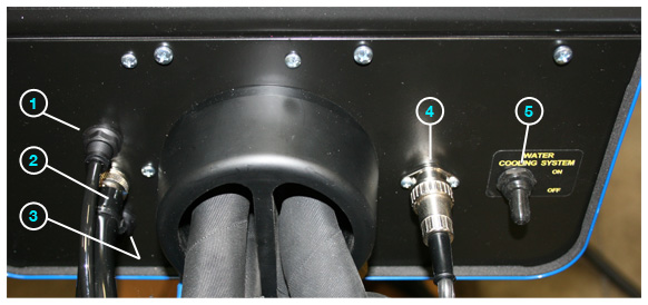
The inverter welders use either 208-240V or 440-480v. It is important to know which level is in question. Look at the Serial Number tag on the back of the cabinet to determine the correct voltage for a given welder. They may be run at maximum power using 3 phase power or on 2 phases (also known a single phase). The indicator lamps on the front panel will glow according to the power available. A phase indicator lamp if lit up does not indicate a proper voltage level – only that voltage is present. Set the breaker in the shop panel to ON and the welder's breaker to OFF. Note the lug layout on the welder power plug. See the three lugs that look the same and the cylindrical pin that is different. The pin lug will be earth ground. Perform the following steps:
- Setup the test meter for measuring AC voltage.
- Plug the welder into the shop outlet.
- Remove the plug just enough to access the plug lugs with the meter probes.
- Measure from 1 to 2, 1 to 3, and 2 to 3.
- Log the three readings on paper. They should be close to each other and at or above 208V. If the test is not successful, disassemble the plug, check the wiring, and make any needed repairs.
- Call a qualified tech or electrician to do further testing if a successful outcome is not found quickly.
Troubleshooting the Spot-Squeeze Gun
The two-sided spot gun is connected to the secondary side of the weld transformer and essentially shorts the output during the weld cycle. The gun creates a very high level of squeeze pressure between the electrodes that is important for a superior resistance spot weld. The standard "squeeze" gun can generate over to 500 pounds of pressure and the high-pressure gun can generate over 1200 pounds at the weld tips through use of a large air cylinder inside the gun. Each end of the cylinder is connected to an airline that runs up to the bottom of the gun through the Command Cable. (The Command Cable is the control link between the cabinet and the gun.)
The electrical connection to the gun is a three-wire configuration where the two triggers share a Common (-24 vdc). The wire runs through the Command Cable. A round, metal, 4-pin connector is used at the Front Panel and an oblong, 3-pin, plastic connector is used inside the gun. A dedicated harness brings the signals directly from the trigger switches to the 3-pin and back to the cabinet and finally to the PCB.
Failure to weld or poor weld
Failure to weld and poor welding due to a problem with the gun may occur by either of two means. First, the gun may fail due to a remote electrical or mechanical problem or second, it will fail due to a local problem with the weld tips.
Confirm the following: squeeze pressure (65 to 80 psi), trigger circuit (continuity at the Command cable connectors), weld cable connections (tight at both ends) and stroking contact points (bushing and piston o-rings are in good shape). The tips must be clean, new or dressed, and setup with the correct shanks and arms for the job. Command cables are normally not repaired because heat and tie wrap pressure mold / melt the components together.
Gun will not Reverse
When the gun will not open, check the trigger circuit. Check continuity at gun and cable connectors. Make sure airflow reaches the gun cylinder. There may be a pinched air hose. Be sure cable bundle tie wraps are loose enough to allow flow.
-
Confirm flow through airlines out to the gun. (Disconnect airlines: 1) at the cabinet and press triggers to open solenoid – hear air blast, then reconnect and 2) at the gun and press triggers again – hear blast again. Replace any lines that do not flow. (Normally the Command Cable is replaced as an assembly when there are problems within it.)Forward gun action is very reliable because the rear air chamber is sealed at both ends by o-rings. Reverse action air may leak past the bushing in the Head (nose) of the gun.
-
Confirm that the following conditions are not causing the problem: melted bushing, tip centering set screws too tight, poor internal o-ring lubrication, no REV air.
Poor squeeze pressure
When squeeze pressure is in question:
Check air pressure at panel gage.
Check for a pinched air hose.
Check that correct electrode lengths are installed.
- gun forward air
- squeeze gun trigger wire
- gun reverse air
- dent puller gun trigger wire
- cooling pump switch
Running out of stroke? Squeeze quality is assured when adequate air pressure and smooth stroking are in play. Effective gun inspections and tune-ups create this situation.
Mechanical Checks
-
Internal Friction - Bushing (Nose-Head)
Set screws too tight?
Overheated-deformed plastic?
Centering maxed out?
X-adapter collar screws dragging?
-
Internal Friction – Stroking Center Shafts(copper and aluminum or steel)
Over shaft tip end surface – rough or dinged?
Piston and O-ring – lube, burned, or dry?
Shaft bent or damaged?
-
Tip (Cap), Shank, Center Shaft Condition
Are they straight with openings and tapers round and smooth?
Is setup length too long (or short) to give good squeeze and release?
Is the fit between parts clean and tight?
Are tip faces dressed and under 10mm?
-
Gun Air Flow & Control
Air Line (Command cable) Integrity - pinched, melted, bundle lay ok?
Air Fittings Integrity – damaged, bent, loose?
Leaks – o-rings, lines, fittings ok?
Trigger – intact, locknuts tight (S-Side Gun too)?
Cooling Sys Integrity – cable jackets and tubing ok (S-Side Gun too)? Manual cool setting works?
-
Cabinet Air Flow & Control
Filters and vents – open and dust free?
Air Hookup / Delivery – grit and water removal functioning? Any leaks? Regulator adjustable?
Electrical Checks
-
Gun Logic and Power – DC and AC loops
Command cable and trigger harness – trigger, wires and connectors ok?
Weld Cables – hardware correct? Lugs clean and held tightly? Cabinet Integrity / Systems-E (some older welders have an ON switch and electro-mechanical power-up gear)
-
Front Panel
Phase Lamps – all 3 lit and bright?
ON/OFF Switch or Breaker – both positions sure and solid?
Trigger Cable connector rings screwed tight?
Display bright and complete? Pushbutton functions working?
-
Line Cord & Plug (Power Supply)
wires strong, clean and tight?
-
Circuit Breaker
ON and OFF positions sure and solid?
Any buzzing or clicking heard?
-
Soft Start Contactor (if applicable)
falls solidly after 3 to 5 second delay.
Panel Switch to ON?
Service Panel Window – Control System Status Lamps
Location: Inside the i4 and PR-2000 tool and accessory tray (under the rubber mat).
Purpose: To quickly determine the status of many internal systems without opening the welder. The welder needs to be powered up. Look down through the window. There are several lights to watch for. The Voltage Indicator windows have three LED lights in each window, while the IGBT and Bus Bar windows have only one light per window.
NOTE: D means diode while the number determines the device's board location.
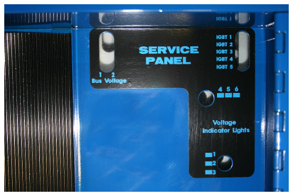
Service Panel Window Control System Status Lamps
Lift the rubber mat in the tool tray to view Service Panel Window.
-
Buss High Voltage OK: LED1 and 2 indicate 300 volts DC present. Both stay ON (but often only one of them is seen unless top cover is removed).
D06 = present
D26 = present
-
IGBT Control System OK: LEDs 1, 2, 3, 4 indicate voltage present across each IGBT gate. Each LED should stay ON. LED 5 (yellow) indicates 15VDC control voltage and should stay ON. These diodes are on a separate, verticallymounted mini-board.
D107 = present
D108 = present
D109 = present
D110 = present
D101 = 15V present
-
AC Input - Voltage Drop Condition: LEDs 4, 5, 6 indicate a problem if any of them comes ON during welding. They all come on briefly during startup then stay OFF.
D23 = Primary voltage drop 10%
D22 = Primary voltage drop 15%
D21 = Primary voltage drop 20%
-
DC Voltage Indicators, LED 1, 2, 3 indicate logic voltages generated and present. They come ON during startup and stay ON.
D10 = 15V present
D11 = 18V present
D12 = 24V present
Frequently Encountered Problems (FEPs list)
-
No Phase Lamps
Check house power level (all phases) at panel breaker and outlet.
Check wires in plug and supply cable.
-
Poor or No Display Text or No Navigation (Phase Lamps are ON)
Check breaker and cassette terminal strip.
Check harness to PCB and 18 VDC.
Check ribbon cable.
Check accidental press of gun trigger.
Check software flash card insertion, version and integrity. (Can not swap randomly.)
Check Display Brightness adjustment. (See Settings.)
-
Check Display Brightness adjustment. (See Settings.)
Check gun setup (squeeze pressure, shank and arm choice, tip condition and alignment).
Check metal prep and condition as well as thickness.
Check Weld settings and Power profile.
Check supply voltage level. (Control voltage drop.)
-
Soft-Start Delay Relay or System not functioning (No weld either gun)
Confirm click on PCB during 5 second soft-start delay period.
Confirm AC Input voltage and Display.
Check for IGBT buss voltage on PCB indicator and system wiring.
Inspect and check Soft Start Resistor Board.
Jumper the relay harness (temporary) to attempt System fix. (May require cassette swap.)
-
No Squeeze Gun stroke / No Weld (Dent-Pull Gun does weld)
Check gun cable connections and trigger (input) loop continuity (24 vdc). (See Command Cable.)
Check pressure and air flow to / through air lines. Disconnect lines at Cabinet and press triggers.
Check solenoid output integrity (24vdc).
Check two-way Gun Solenoid. (Constant stroke air with power OFF means stuck solenoid.)
-
Weld Condition Error Message Issued (No weld at guns.) / Poor voltage or burned part.
Confirm supply voltage to welder. Bridge in high current section generates 300 VDC for IGBTs.
Confirm IGBT buss voltage indicators. Soft Start is normally ok.
Confirm PCB 15 VDC and IGBT driver integrity (inspect bottom).
Check stud diode array on weld transformer. This is a simple at-gun measurement.
Check IGBTs. Bad diode will damage IGBT// Breaker may trip. // May require cassette swap.
-
Pop Sound Reported in Cabinet (No Weld either gun and Soft Start Relay OK)
Inspect systems to locate pop source following input voltage check.
Check for loose wiring connections, especially high current paths.
Check for problem with Soft start or IGBT systems. (See also Item #6.)
-
Temperature Error Message Issued or No Air Cooling (Could involve either or both guns.)
Check sensor Display readout (100 C =failure / 30+/-ok) Also see ambient / outdoor temperature.
Check sensor input (25000 +/- ohms). (Sensor failure or temporary overheat will disable welder.)
Check 15VDC and PCB.
Check solenoid output and wiring.
Check 24VDC and PCB.
-
Cabinet Circuit Breaker Trips
Check breaker and high current wiring. (See Items #6 & 7.)
Check for loose or broken connection.
Check Soft start, bridge, IGBT and diode circuits. (Module may conceal burn.)
-
Facility (wall) Breaker Trips
Check outlet and plug. (Usually a problem outside or near cabinet wall.) (See Items #6 & 7.)
Check breaker and high current wiring. (See item 9.)